Chinese "Shiny Brick"
Repairing an SMPS
This power supply (not yet pictured) is what I refer to as a Chinese shiny brick power supply. They are ubiquitous on eBay, and like all eBay items, the quality is suspect. On that topic, one good brand to look out for is MeanWell; they're actually built pretty alright. Beware of counterfeits and lookalikes such as the MegaWatt brand, who kindly uses the same logo as MeanWell, comprising a stylised "M" and "W".
This individual supply, branded "Hwele" had an output rated for 13.8 V at 25 A DC, and was sourced from somewhere more reliable than eBay. When purchased, it was tested and pushed right up to its rated current and was seen to hold the output steady.
It was my main supply for driving my ham radio equipment and passed away completely silently.
Initial Symptoms
Powering up a piece of connected equipment caused a rapid ticking sound from the supply. The equipment powered up successfully. The sound was the same sound the supply made while it ran itself down just after the mains was removed during normal operation.
After a few seconds of making this noise, it just stopped powering the radio equipment up.
Inspection
1: Capacitors
The supply was opened and had a fairly quick once-over with a keen eye. I was looking for the holy trinity of faults:
- Blown fuse
- Bloated (or ballistic) capacitors
Dry jointsI hadn't removed the board from the housing yet
What didn't take a keen eye was the bulging on one of the capacitors which filters the rectified mains:
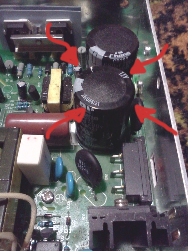
On a quick side note, look at how disgusting and unprofessional that board is. It's filthy.
Obligatory safety note: Rectified mains is dangerous enough, let alone capacitors smoothing/storing it. Such capacitors have no problem sleeping at night knowing they've taken your life. Treat them with the respect they deserve.
For reference, here's a quick diagram of the situation we're looking at:
(Valid only for 230 VAC operation)

325 VDC  O-----+----------+-----O 325 VDC (smooth)
(rectified     |          |
 mains)     C1 680µF   R1 100kΩ
               |          |
               +----------+
               |          |
            C2 680µF   R2 100kΩ
               |          |
    0 V  O-----+----------+-----O

Capacitors 200V 85 °C
Resistors 1W likely carbon film
The capacitors' voltages were noted to be near zero while the unit was unplugged, which indicates some bleeding was occurring During operation, C1 is near 0V and C2 is near 216 V. Something is not right; these should be balanced.
Interestingly, the bulging capacitor is C1, not the over-volted C2.
2: Bleed resistors
A faulty bleed resistor could cause such symptoms. If C1's resistor was fine and C2's was open, then C1's voltage could be held down near zero while C2's is allowed to build up to the full DC rail voltage.
Resistance checks of the two bleed resistors (while still on-board) shows R1 (bleeding C1) was fine, while R2 was way over-value. Hooray, we were right!
It looks like C1 would have had some AC across it. Heading up to the peak of the pulsed DC input, C2 would be charging through R1. C1 would also have a few volts form across it equal to the drop across R1. So C1 and C2 are both in the correct polarity. At the peak of the cycle, C2 would be charged to 325 VDC, and C1 would have no voltage across it. After the peak, as the rail falls, C2 would still have 325 VDC across it, but C1's positive end would be falling lower than this, so C1 would have a negative voltage across it. Not good for it at all, and the most likely cause of the bulging.
3: Eh? It's balanced again?
Powering the device up on day 2 shows a nearly balanced voltage. We had 165 across one capacitor and 171 across the the other—that's a 49/51 split, pretty near balanced!
Alas, the unit was still not powering up. When mains is applied, the output voltage rises to a volt or so for a brief period less than a second.
Current hypothesis is that this is the kick-start oscillator firing for a few cycles. If so, the main controller chip is either borked, or is choosing not to fire up the supply. I have my money on the latter.
It will be interesting to perform a better diagnosis of this before pulling the board out and semiconductors off their heat-sinks. Investigating ripple will show up a bad capacitor for good, so it's time to get more insight than a multimeter gives.
4: Fused neutral
It was noticed that the fuse was put on the neutral side of the mains, which is strictly illegal in any country with a wisp of electrical standards. Same goes for switching the neutral. Same principle. Yet chinese equipment consistently gets it wrong. On the bright side, at least something's consistent.
5: Scoping for ripple
The supply was floated on an isolation transformer. A stand-in for R2 was temporarily wired into place and the intersection between C1 and C2 was grounded Two 100 W 230 V light bulbs wired in series were put across the capacitors as a whole and the voltage on the 0 V and 325 V rails was scoped.
The summary is that the ripple seemed to be fairly even. This indicates both capacitors to be comparable in spec. It looks like I've escaped replacing (very expensive) capacitors, phew!
6: Power transistor tests
With that hypothesis out the window, it's time to pull out the multimeter and start systematically probing stuff with the diode and resistance settings. Didn't take me long to find a bit of an anomaly between the two main switching transistors that switch the rectified AC into the main transformer. One of them had no measurable diode effect and presented roughly 150 ohms of resistance across both the E-B and the B-C junctions. Pull it out!
The cause of this is unknown, but it was likely due to an unpopulated space on the PCB which, if populated, puts a MOV across the mains just after the common-mode filter. A MOV in this position would conduct when a spike coming down the line reached it, mitigating the damage to components downstream, such as switching transistors. It's especially important to remember that if the component which conducts the spike is after the recitifer (which is near certain in this case), that the bridge rectifier also has to conduct the huge current that may be involved. So it's by far best to place MOVs as early as possible.
The transistor turned out to be a mysterious bugger with the part number 20A400. The only datasheets I could find using this part number were rectifier blocks... not what I'm looking for at all. The best we could have surmised was that it was a generic Chinese transistor, and believe that a current rating of 20 A and voltage rating of 400 V wouldn't be far off the desired figures for a transistor in this position. It's likely this model of transistor is some generic Chinese thing.
I could have reverse engineered the supply a bit further to work out what a suitable replacement would be, but I opted for the easier option. A supplier of this transistor was found on the interwebs who shipped 10 of the things for about $1 each. Confidence in the performance of the things when they arrived in the post was a bit higher than if they we purported to be Dallas or Analog or something. After all, who would fake a Chinese transistor?
Each transistor had its current gain measured and were individually pushed up to near 400 V across E-C. Since the magic smoke seemed to stay within the confines of the casing, the one with the best Β was swapped out for the dud. If these transistors do ever fail again, it shouldn't be catastrophic and will at worst take the fuse out. The rectifier as well if it's having a bad day.
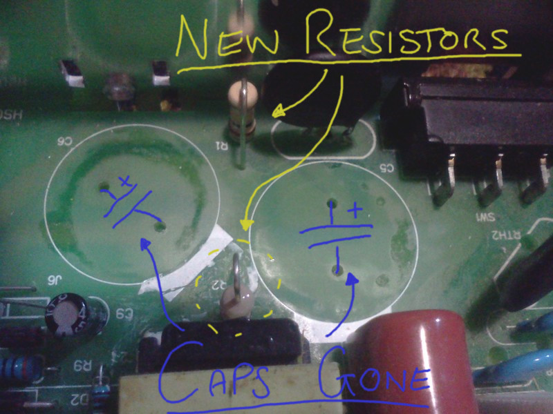
6: Replacing some stuff
Both of the so-called 100 kΩ bleed resistors were ripped out (carefully desoldered) and suitable replacements were chosen from a reliable supplier. You know the type, resistors that actually hold their value for more than five years. Yeah. Those ones.
Also replaced at this point was the dud transistor. It was replaced with one of the China-sourced replacements. Like I said, I don't think anyone would seriously try to hock off some repackaged BC548s as 20A400 weird-ass Chinese power transistors for which there is no demand. Any con artist with a brain would at least try and label them as something which the west is lapping up.
Aside from this, I hold little doubt that these transistors are up to the job, and that the reason for failure was like not poor quality transistors, but instead a spike in the line which crippled the transistor.
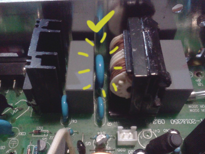
A MOV was also inststalled where the manufactuer left one out.
Although one looks a little odd, both of the capacitors are at least matched. To me, the bulge looks like more of a structural thing than a gas build-up. I'm prepared to wait until one goes up in smoke before I replace them.
7: Testing the TL494
The TL494 is the heart of this supply, providing a flip-flop with dead-time and an oscillator and all sorts of other goodies for running a SMPS. It'll be a good idea to check that this thing is still functioning before going and powering the supply up. (As a side, this is actually a really cool chip and I recommend the datasheet for a good, interesting read.)
I can just picture powering the supply up and finding that the new transistor and bleed/balance resistors are working excellently. Then, quickly finding that the TL494 is switching at 100% duty cycle or something stupid, pushing:
- the output up to 100 V (or something else horrible)
- capacitors into the ceiling (or my face)
- magic smoke out of tens of components
...so it's best to play it safe.
This supply has a trimpot for the adjustment of the regulated voltage. This meant that I could just use a dual-rail +12/-12 V supply I had lying around to both power up the TL494 and provide a voltage on the feedback path for the TL494 to "regulate" towards. It was about 6–8 months before I had a chance (read: got off my arse) and performed this set of testing. Using the -12 V rail as ground, I powered the TL494 off 24 V and squirted 12 V into the power supply's output. Twiddling the trimpot proved the TL494 and its peripherals were in working order with the switching duty varying between zero and about 95%, with deadtime looking correct. Perfect!
8: Power-up tests
With the TL494 and everything up until the main switching transistors, and the filter capacitors all in working order, it was time to power the unit up. In series with an incandescent lamp (they're still useful!), the supply was hooked up to isolated 240 V mains. The power indicator came on, and everything seemed to be working. A bit of scoping around the main transistors confirmed near-optimal performance. Running without the heatsink of the case, the replacement transistor was getting a wee warm-hot while its mate was luke-warm to cold. A bit of scoping, and it seemed that it was not being switched off quite as hard, spending more time in its linear region rather than in saturation, hence the heating.
Switching over to 115 V mode and floating an auto-transformer worked fine, but after a few minutes, showed a few problems up. The supply started to make a rather unsettling noise. This time, the transistors were both cold.
Measuring the voltage across each filter capacitor shows a worrying imbalance: ~150 versus ~60 volts. However, the lightbulb in series with the mains side of the supply wasn't lighting; no excessive current draw.
9: Rabbit holes
At this point, it's a good time to recap:
- Capacitors were proven to have similar characteristics
- Main transistors were tested and a shorted one was replaced
- Both bleed resistors replaced due to one which went open
What could be causing this imbalance then?
Ruling out excessive current draw, it must be that there is resistance in the path between the mains and one of the capacitors. But where?
Some low-voltage, medium-current tests were perfomed on the unrectified mains side in order to track down this resistance. Everything checked out. Hey, but what if the rectifier had gone, that might cause one of the DC rails to be lower than it should be, right? More low-voltage tests confirm the rectifier was perfectly fine.
Getting late, need sleep. The fault probably settles in when there's high voltage present, so voltage tests during operation seem to be my best option.
Thus was the rabbit hole.
Luckily, discussing and thinking about the problem led to the actual solution. What if, in the months between testing the capacitors, and actually seeing this new fault, the capacitors' condition changed? Plausible.
An averaging meter should read about 63% of peak when measuring half-wave-rectified DC. So we should expect ours to read about 70 volts if the capacitor was completely open. Include some losses to diode bridges and bleed resistors, we're approaching the approximate 60 V and it's now clear where the fault lies. It's that pesky capacitor with a bruise on its head. I knew it'd come back to bite me eventually, it's good to catch it this early I guess. Both capacitors are now removed and replacements are being sought.
10: New capacitors
Replacement capacitors are installed, firing it up seems promising. Adding load sees the power supply making a noise it has never made before. When healthy, it would make a quiet switchmode hum under high load, however it was now making a loud, irritating squeal under a load of only 5 A. Something is still off. What about that transistor that was getting warmer than its counterpart?
11: Warm Transistor
Feeling the warm transistor (Q1) under operation (isolation transformer!) showed that it was still warmer than Q2. Something still isn't right with this supply. Warmth would indicate that perhaps it isn't being switched as hard, leaving it in its linear region for longer than Q2. It's back to the split 12/24 volt supply for more testing of the driver stage.