Fast Edge Generator
Background
I've been designing a JTAG level shifter to extend the 3V3 capability of my Bus Blaster up to 5 for a keyboard I've been reverse engineering lately. Since I've decided to go with passive MOSFET-based voltage translators (LSF0204), signal integrity is a factor of concern. In order to perform some basic checks on the signal degradation through this level shifter, I decided to dig out an old PCB I had designed based around the oscillator that Alan W2AEW shows in some of his YouTube videos for TDR (time-domain reflectometry).
Designed around the 74AC14/74ACT14, the buffered square-wave oscillator Alan shows, displays very fast edges. This makes it especially suited to TDR among other things. Alan's videos on the oscillator (and really any videos on his channel) are definitely worth the watch for the electronics or radio enthusiast. Check out his YouTube channel.
Digging out an old design
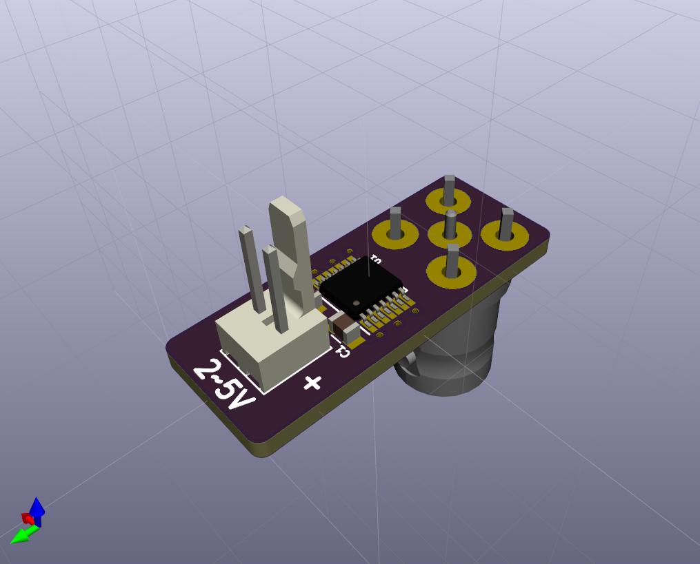
I decided that in order to characterise the distortion that the LSF0204 introduces to my JTAG signals, it would be a good idea to dig out an old PCB I had designed in August 2019 a little over two years ago. I had designed the circuit and routed a PCB in Kicad, based around a CR2032 cell for power, but never had the board fabricated. Fast-forwarding to 2021, I decided to replace the CR2032 holder with a Molex KK type header, choose a smaller package for the 74ACT14, and reroute the board for size. The result is a nice little stick, not much wider than the through-hole BNC connector at the output.
Top side:
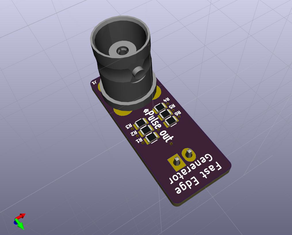
Bottom side:
I had originally planned for a nice self-contained unit with a 3D printed case and CR2032 coin cell to power, but decided against this for ease of powering from different voltages for different applications. In theory, the circuit should be able to operate anywhere from approximately 2 volts up to a little over 5, giving more flexibility (and runtime) than a coin cell while losing the inherent isolation which battery operation affords.
The boards were fabricated with OSHPark within a few days (they had a free-of-charge upgrade to a quicker service tier since they had room on a panel). They spent the better part of a month in USPS's hands, beaten by many China Post packages I ordered at the same time. Covid and all.
Probing the prototype
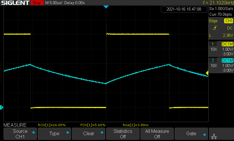
While I wait for the parts from Mouser, I decided I'd scope a breadboarded relaxation oscillator with junk bin parts: SN74AC14, 47 nF, and 1 kΩ, decoupled with 10 nF. I expected far worse signal condition than I got, considering I'm probing nanosecond edges being squirted into a lightly loaded breadboard strip.
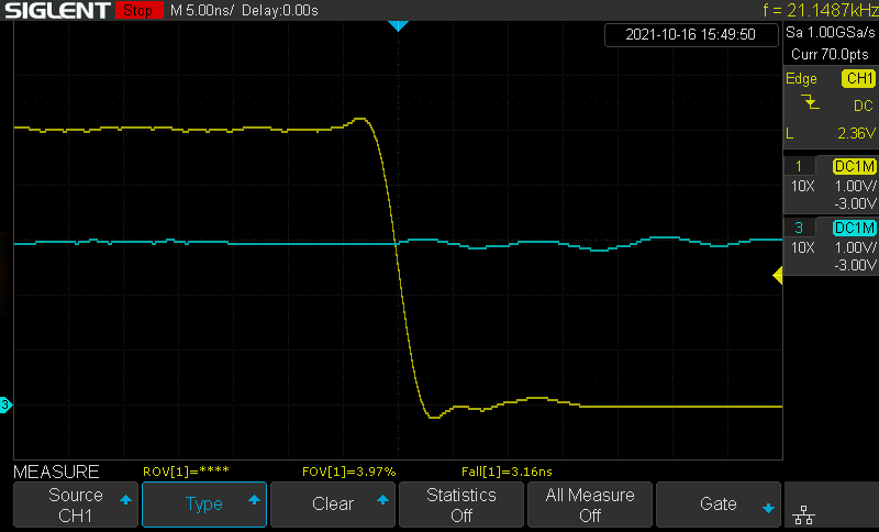
CH1 in yellow is the gate output, CH2 in blue is the input. The IC exhibits approximately 1.5 V of hysteresis, resulting in an oscillator of approximately 21 kHz.
Zoomed into 5 ns/div, we can see the ringing interacting between input and output:
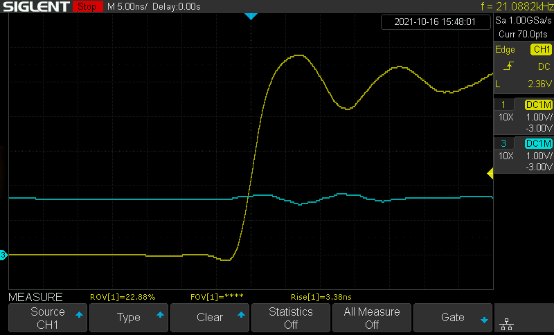
That's some significant overshoot on rising edges (approx 15–20%), but falling edges look a bit cleaner:
All in all, the edges are about as fast as the scope's own rise time of 3.5 ns. This is plenty fast enough for most applications, but it'll be interesting to see how measurements on the first revision PCB compare with respect to the ringing/overshoot.
I don't anticipate the rise time being increased too far by the 50 ohm output impedance (shared across 5 gates) in the first PCB revision. The outputs have a fairly strong drive capability of 50 mA, with the package overall capable of 200 mA. If my hypothesis is correct, I'll have to borrow time on a faster scope to measure it more accurately. I've seen people get values of a few hundred picoseconds out of this IC which requires something in the realm of a GHz scope.
First revision PCB
I built one of the Rev 1 PCBs (photos of the board to come). I probed the BNC connector pads directly before soldering one in, and the signal is measurably cleaner than the breadboard prototype - I'm really happy. The rise time remains the same, at least measured on a 100 MHz scope (i.e. it's not become measurably worse than the scope rise time).
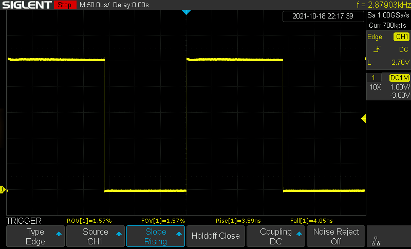
Here's the board without BNC, completely open, showing the pulse train looking pretty clean:
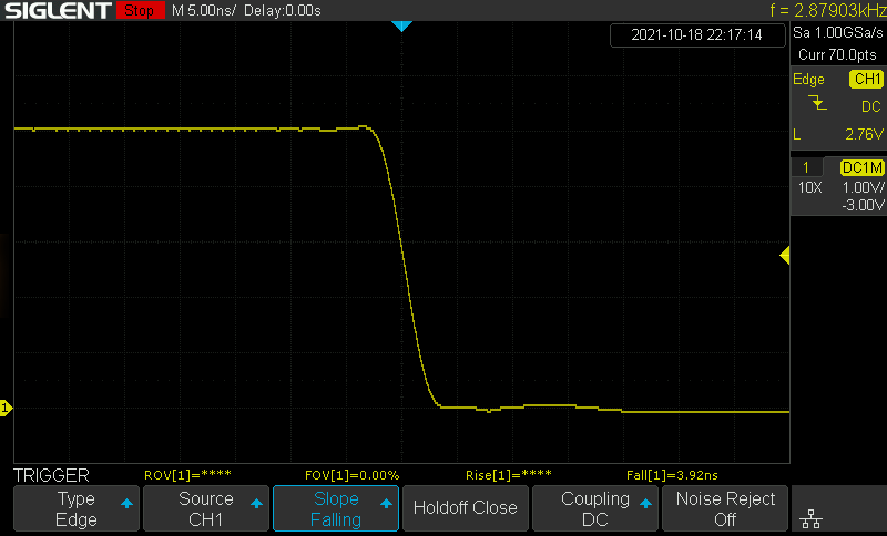
The falling edge looks around as clean as the breadboard prototype:
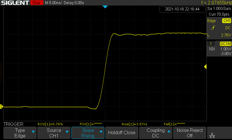
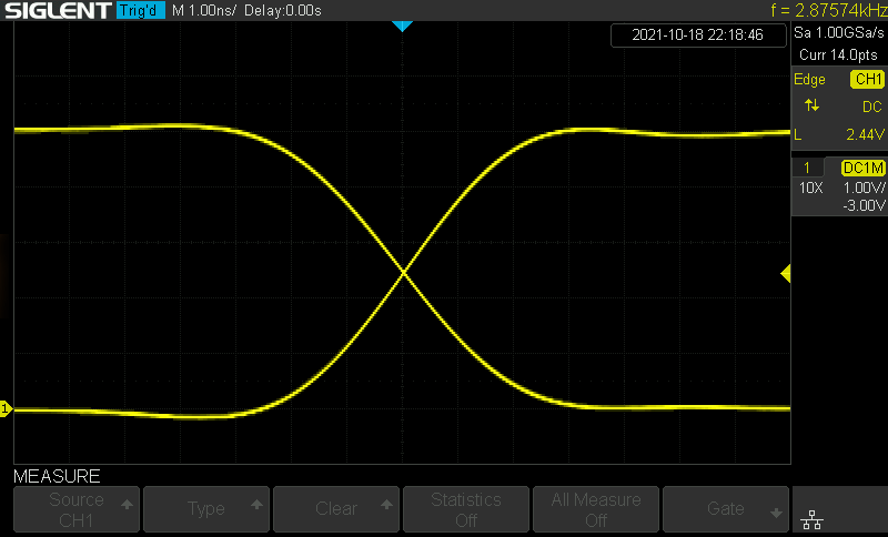
But just look at that rising edge! Far less ringing:
Plus an alternating trigger glory shot zoomed in further than this scope deserves:
Coax Measurements
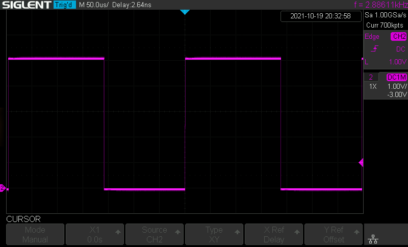
Running into an open line is pretty useless, so once I got some BNC connectors sorted out, I promptly soldered one in and attached a line and a scope with a BNC "tee" piece. You can't see much when zoomed out of course:
However, once you speed up the sweep a bit, everything becomes apparent:
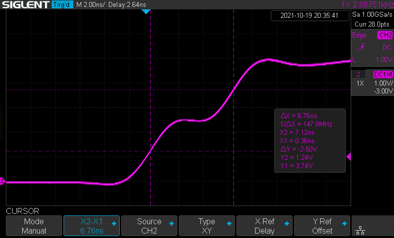
The oscilloscope is seeing the TDR pulse generator's edge rise until it meets a 50 ohm characteristic impedance transmission line, at which point it can't drive any higher than about half of VDD, so 2.5 V. After this, the edge goes on its merry way down the transmission line, meets the open end, and reflects back on itself, adding onto the rest of the pulse/cycle still travelling down the line to form 5 V. It travels back toward the oscilloscope, ploughing 2.5 V up to 5 V wherever it goes, eventually reaching the tap-off point going to the oscilloscope where we can measure the time delay between the edge going out on top of a quiet 0 V line, and the edge coming back on top of a 2.5 V pulse on the line. I.e. we can measure the amount of time it takes an edge to take a round trip of the line.
What blows my mind every time is that we're saying "screw the speed of light, I can sample at higher resolution than it takes for an electrical impulse to move a metre!" - it's the ultimate middle finger to the universe or something like that.
Regardless, the maths with my first few attempts works out about right, after I realised the strange 7 cm offset that seemed to be added to my measurements was really the round trip distance from the centre of the tee adapter where the scope was connected, to the line side of the tee. With a fixed offset of 3.5 cm each way accounted for, the maths on the shortest line I can measure with this setup becomes:
rtt = 6.76e-9 s
c = 299792458 m/s
VF = 0.66 (Cheap RG178, assume PE rather than PTFE dielectric)

rt_dist = rtt * c * VF
        = 1.338 m
length = rt_dist / 2 - 0.035 m
       = 634 mm
Measured with a ruler, the coax is somewhere between 630–640 mm long. It was made of two ~300 mm SMA patch cables joined together, so there could be some inaccuracy of the 66% velocity factor I've assumed, depending on the insulator in the connectors and joiners. However inaccurate/coincidental my results, it's thrilling to see I'm at least in the ballpark let alone potentially within a centimetre.