Breadboarding an SOT-89
Nothing much, just a wee little hack I did to check some components I saved from an old board were still working. I'd recommend using purpose-built boards and adapters for more expensive things.
This bodged method was just a quick, easy way for me to test out some less expensive (free) components.
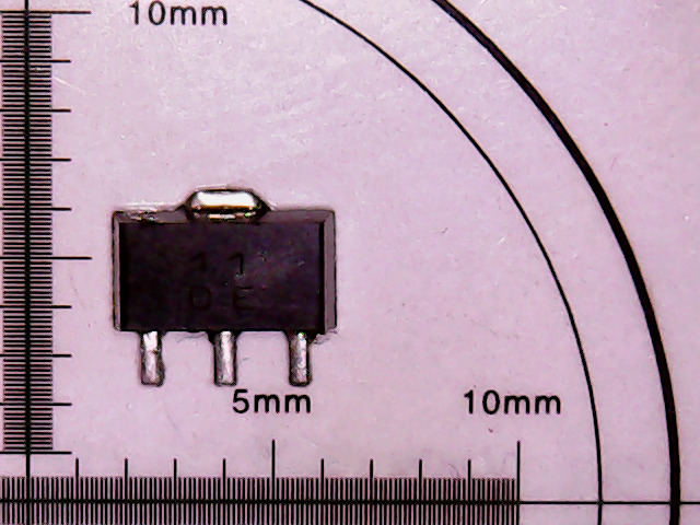
Here is a "11DE" from what I can tell. All of the SMD dictionaries I've tried can't actually give me a more meaningful part number from this abbreviation. However, from looking at where in the circuit it lied, I was able to deduce it was likely some form of voltage regulator.
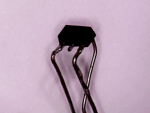
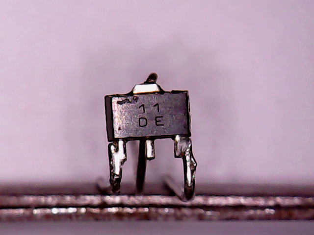
I dived into my pigtails jar and bent up three leads for the thing. Bending and soldering the leads took all of about 2 minutes.
On the board
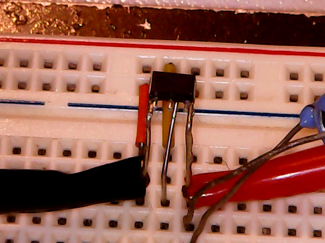
I was then able to plug the thing into breadboard. In the first picture, it is difficult to see since SOT-89 packages are only about 2x4 mm, but off in the top left corner is the so-called "11DE" device. It blends in with the black IC clip under it, but it's to the left of the yellow and orange jumpers. Trust me.
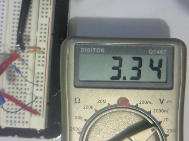
Seems like a 3.3 V regulator from what I can tell. Something interesting to note is that it doesn't appear to require an external load in order to regulate. I was able to completely remove my external 1 k resistor and it kept at 3.3 V, regardless of input. This might be a fluke, or it might actually have this taken care of internally.
For what it's worth, the pinout:
     ____
  __/____\__
 |          |   1: Ground
 |   1  1   |   2, Tab: Input
 |   D  E   |   3: 3.3 V Out
 |__________|
  ||  ||  ||

   1   2   3
Like I said, I was unable to find a meaningful part name, let alone a datasheet for this thing, so I have no idea as to the maximum input voltage and dissipation. All I know is that it will run to at least 12 VDC input as this is what it was doing in the piece of computer equipment it came from.
Misc ramble
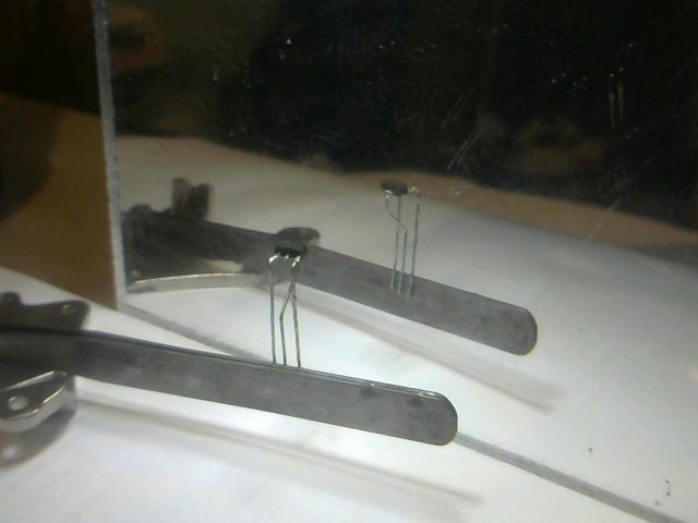
Here is a bit of a better look at the jig I use for holding stuff like this under my microscope. I have too many neodymium hard drive magnets lying around doing nothing, so they find use holding screws and making things (tweezers in this case) magnetic so they can hold things.
I also keep a small plastic mirror behind in order to help soften and reduce any shadows from the ring light.