Breadboard Power Adapter
If the PCB design's copyright date is accurate, back in 2014 I designed my first PCB destined to be made "professionally".
I found myself often without the convenience of a bench power supply and in need of something to power some 5 V stuff. I enjoyed the lack of need for hooking a bench supply to my stuff when using the Atmel-based Teensy board. This uses the power from the USB programming cable and feeds your breadboard's rails too. What a good idea…
The Design
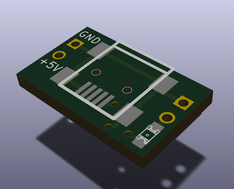
I came up with a quick design in October 2014 and forgot about it completely until mid-2015 when I got to work preparing the tiny single board for an initial production run. It's very simply board with a USB mini-B receptacle and some header pins to plug into breadboard and power it up. Thrown in there as a bonus is an LED to show when there is power on the USB connector (and the rails).
There are two pairs of header pins, one on each side of the USB connector. Each set of header pins carries GND and 5 V in identical polarity. The reason for doubling-up on the header pins was to add rigidity to the assembly when it is plugged into a breadboard.
The LED's pads are visible on the image above in the bottom-right corner of the board. Its resistor was placed on the underside of the board to save space. Also on the underside of the board is the main track of copper between the two 5 V rail header pins. The via which connects this to the USB connection is visible at the bottom-right corner of the USB connector.
I was always in two minds about adding a polyfuse to the board. From a safety perspective, it would make sense to limit the current to 100 mA (USB spec max) although there are chargers and ports which will deliver more than this, so it may just become another wasted component that people put a jumper over. I was very reluctant to add a larger polyfuse such as a 1 or 2 A one, as this may be taken by some as an indicator that a USB port upstream of this board can supply this much. In the end, it was simpler to leave a polyfuse off, and trust the users of these boards for once.
In retrospect and after learning more about PCB design, I should have had a small concern about the placing of the LED so close to the 5 V header pin. Had these not been hand-soldered, I would now not be surprised if I had a tombstoning problem. Regardless, there is also no need on these boards for the large width of the copper between the LED anode and the 5 V header pin. It would also likely contribute to any tombstoning by providing a better path for heat leakage out of the anode's solder pad.
No worries though, the Rev A boards turned out just fine, and this gives me room for improvement if I move production beyond this small run of ~100 pieces.
Tiling
It will clearly be more cost-effective to get plates of multiple boards made than getting an equivalent quantity of individual 11×18 mm boards made up. That would just suck.
The PCB house I got in touch with had pricing which made a 50 mm square board the most cost-effective option for this small run. I was able to fit ten boards onto a tile of this size.
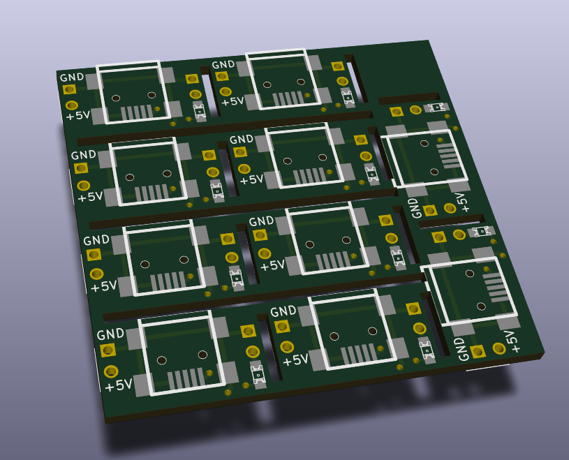
First things first: it lacks tooling strips of any kind. I decided to leave tooling strips off to save space. These Rev A boards are a for proof of concept and the very first run and would be assembled by hand. This meant that I could leave tooling strips off and squeeze the most out of the limited fibreglass real estate I had.
Boards in the mail
I got my boards in the mail within a fortnight or so. I ordered ten copies but received eleven. Going against the computer models of the boards above, I opted for the trend at the time and ordered my boards in red rather than green.
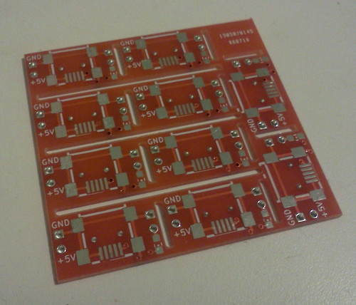
These were easy enough to snap out. A few strokes with a hacksaw blade to the fibreglass on the the left hand side meant that I could snap the rest of the boards out and apart. To get the bonus workmanship XP on offer, I did a quick pass with a file to clean up the snaps.
I only snapped out 60 of the boards. Ten for the initial run and a later 50 for the public if the initial run went well.
Population
I decided to populate the 60 boards after snapping apart rather than before. This basically came down to the fact that the USB connectors overhang the front of the board and might get in the way of the saw blade, especially on the two boards on the right-hand side of the tile which are rotated -90°.
I had already procured:
- 100 USB mini-B SMD sockets
- 200 2012 (0805) red SMD LEDs
- A lifetime supply of 2.54 mm pitch header pins
I would leave the resistors until last. In the initial design, I had chucked in a 1 kΩ resistor. I pulled the value from somewhere rather unpleasant and wanted to refine it once I had the LEDs and could evaluate their brightness against the red boards.
Soldering was nothing interesting enough to write about here. Solder paste was applied to the pads for the USB connector and LED, then each was hand-soldered in that order.
I then got in there with an ohm wheel, hooked up the power and picked out an appropriate value for the LED's current limiting resistor. 3.3 kΩ was the winner in my attempt to balance adequate brightness with low current draw. After all, a single USB socket is only meant to provide 100 mA without software negotiation (future project?). If someone was going to be running their project off a USB port, they'd rather I was trickling 1% of that total current into the LED than me pissing 10% of that down the LED to get it just a little brighter.
For the gentlemen that enjoy a bit of theory, an average red LED will have a forward voltage of ~1.8 V. Recalling USB's nominal supply voltage of 5 V, this leaves ~3.2 volts across the current limiting resistor. Take one Ohm's law capsule three times daily with a meal and you'll get 970 µA as the LED's forward current.
Of course this business about a 100 mA maximum current draw is not always the case with USB chargers for phones, where you can often pull amps. No guarantees that the USB spec connectors will facilitate this without catching fire. Although, I should note those smaller USB micro-B connectors are used on phones which pull an amp or two while charging.
Rounding it up
All in all, this has been an interesting (and useful) project for me. I have room to move forward with a revision B board. Although, a Rev B would only be necessary if I were to move forward into mass production where pick-and-place machines work together with reflow ovens to create tombstone masterpieces. Until then, this initial revision seems to be performing well and I find myself using the convenient 5 V USB power I have so readily from computers and chargers more and more often whenever I have an "I wonder if…" moment, or a sudden "Let's check that theory" brainwave. Very handy little board and I'm very happy that I find something I made myself so useful.
Even though it's such a simple little board, I am working on publishing the plans so other people can make their own if they so wish.