HP 53131A Counter Repair
I rescued a HP 53131A 225 MHz universal counter from being put in the proverbial dumpster. It fails the power-on self-tests despite being in cosmetically good condition. Here is the unit greeting me:


Twice or thrice, I was able to have it pass its self-tests after being plugged in idle for a few minutes, but I haven't been able to demonstrate this with any reliability. Being intermittent makes it sound like a scratchy solder joint, bond wire, or similar.
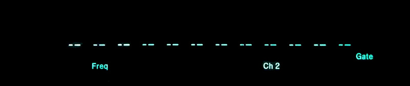
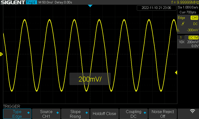
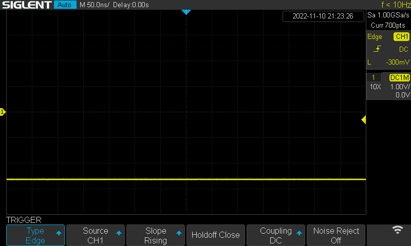
The "SELFTST: FAIL" screeen can be dismissed and the counter configured for use. Channel 1 appears to work well enough in basic testing, but with a 10 MHz signal applied to Channel 2, the unit never triggers:
Initial inspection: wat
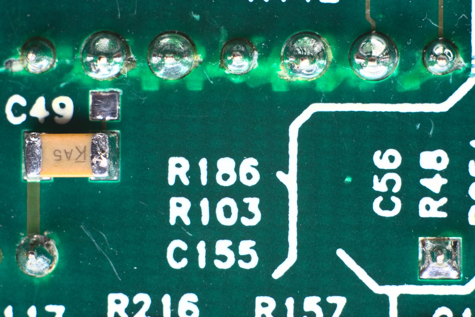
I found this resistor which clearly had second thoughts during soldering 20–25 years ago. Nerdy version of Where's Wally - can you spot it?

How about now?
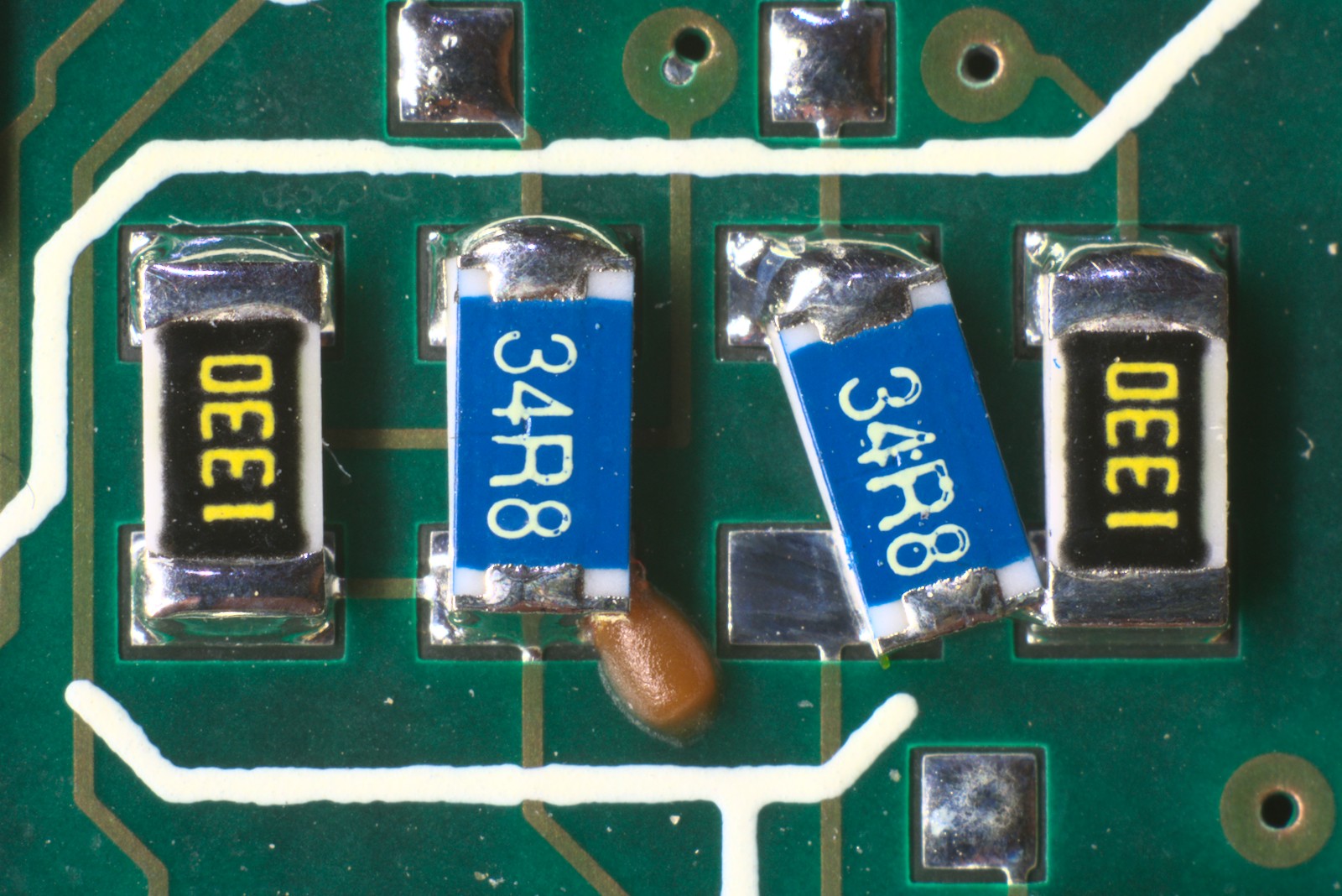
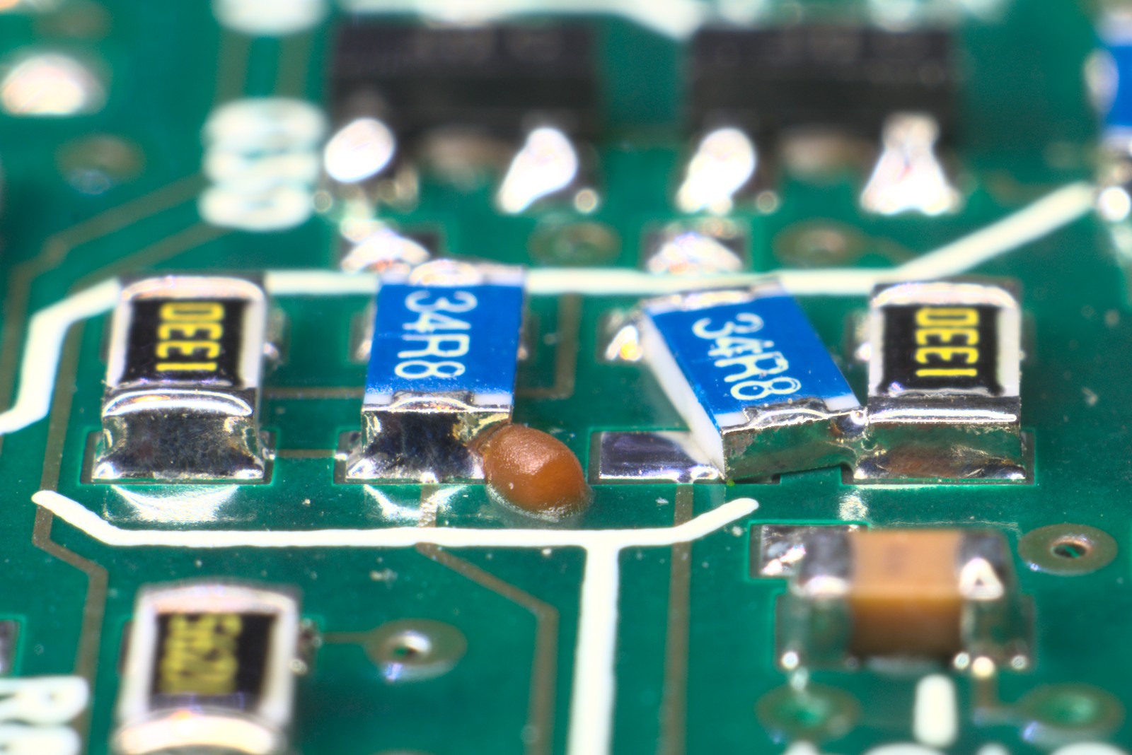
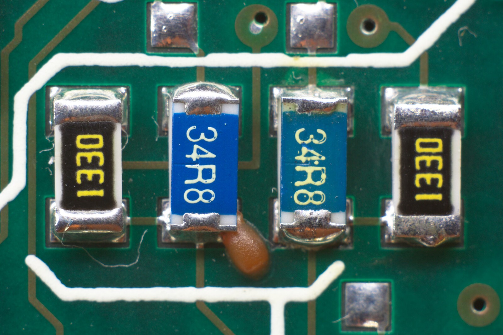
Electrically it's fine - the wonky resistor is soldered to its mate, and underneath it, there is a trace that was joining these two onto the same net anyway. The orange-brown blob looks to be a piece of glue that was probably supposed to be underneath the wonky resistor to hold it in place during the soldering process so it wouldn't wander...
But there's no surprise that it would have passed flying probes and higher level testing. Hopefully today, automated visual QA would inspect the job and reject this board. Much prodding later I concluded this unsightly mess is not the cause of CH2 failure.
Digging shallow: boring
First things first, power rails where they come from the power supply board onto the main board checked out fine. I verified the power rails along the frontend amplifiers and they checked out fine too.
Digging deeper: hmm
The next course of action was to squirt the 10 MHz ref out of the back of the unit and into its CH2 input (eerily reminiscent of the Slurm Queen in Futurama, S1E13). Following the signal path through the frontend should show up the problem.
Here's a simplified diagram of the frontend of the instrument:
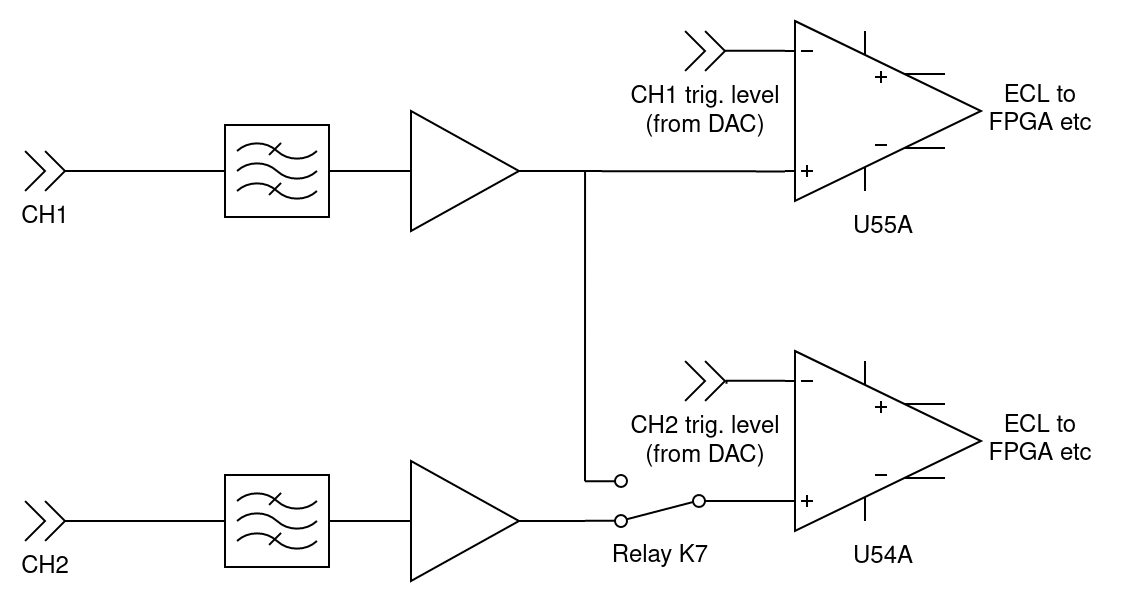
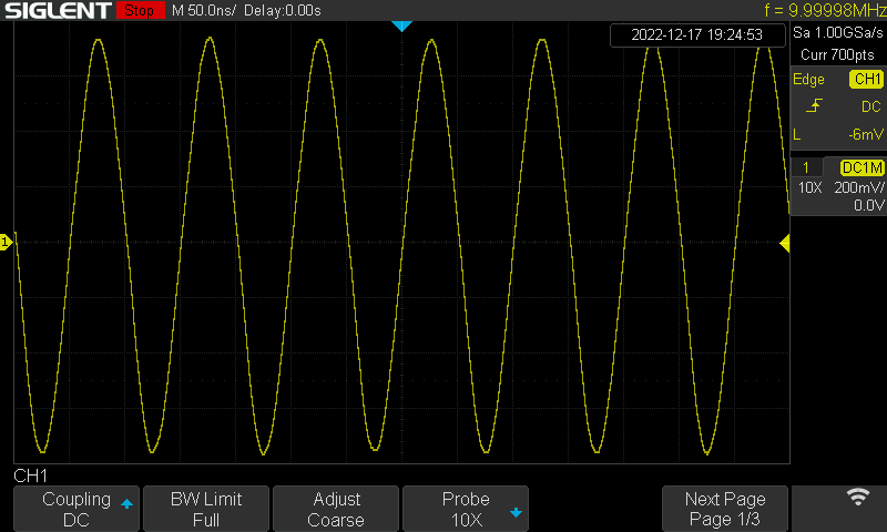
Here is the last time the signal looks as it should. This is just after the R103-R142 divider, which forms the output of the main CH2 frontend amplifier:
Here it is on an input at the next IC in the signal path, an ultra-fast complementary-output comparator U54-A:
Suddenly going from a nice zero-centred 1 V pk-pk waveform to -2.7 VDC is strange. The only thing in between the points these two plots were taken is relay K7. This relay allows the microprocessor to choose whether CH2's comparator recieves CH2 or CH1's conditioned signal. Its default "off" state is to patch CH2 through, and checking its coil shows it's deenergised, meaning it should be patching CH2's frontend to CH2's backend. When energised, this relay enables the COMMON 1 mode to perform fancier single-channel time interval measurements by repurposing CH2's trigger and counter for CH1 operation. This is used for example to measure CH1 duty and other such single-channel short-time-interval parameters.
My thought now is that the input to the comparator has become internally shorted/shunted due to overload, and K7 is/was soaking up the difference.
A quick resistor-to-ground confirms the opposite case. Using a mere 100 kOhm to ground, I can lift the input of the comparator from -2.7 V to around -30 mV. This indicates that the input isn't shorting or shunting, and in fact the relay has gone open. This explains why the fault is intermittent - super iffy/scratchy contacts. Resistance checks on the normally-closed pair of contacts shows it varying from kiloohms to megaohms and beyond.
Checking the solder joints on the relay without—and then with—magnification shows them to be fine. Excuse the scratches/dents from my probe tips.
Square on: 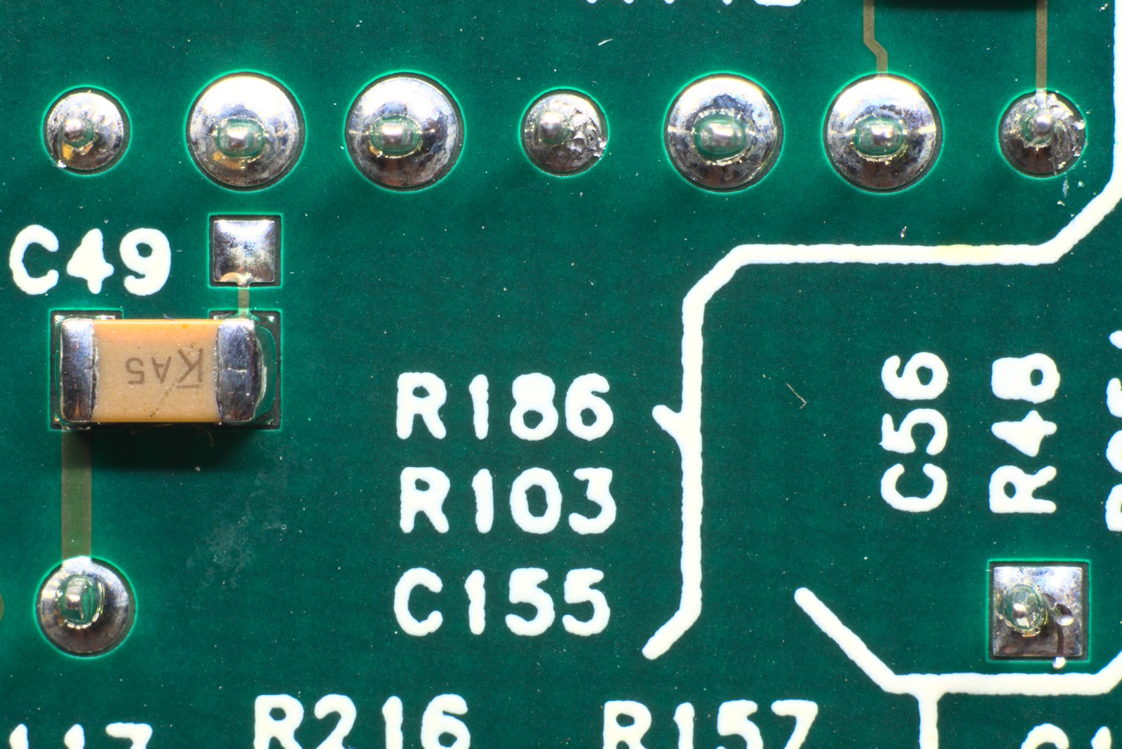
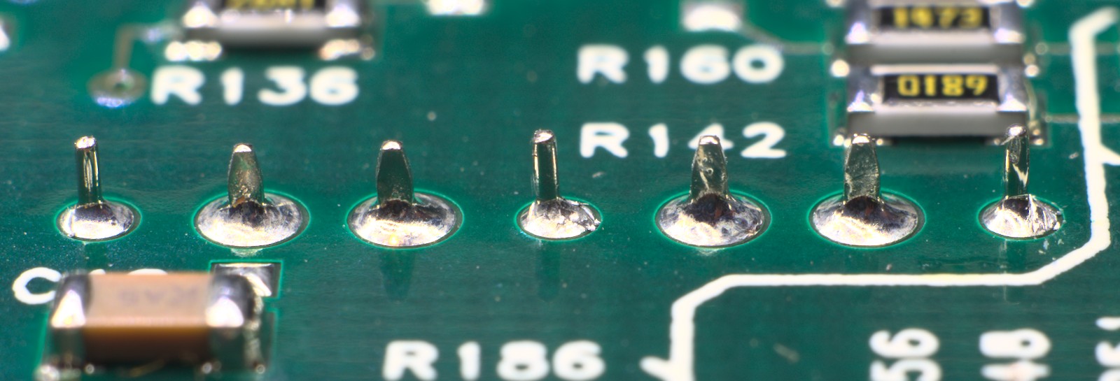
Row of seven signal and ground pins, side on:
Two pins for the coil (extreme left and right), side on:

Maybe one day I should photograph the setup I use to get these shots. The proportions are ridiculous to get this sort of magnification with a regular camera!
Here's a mugshot of the main suspect:
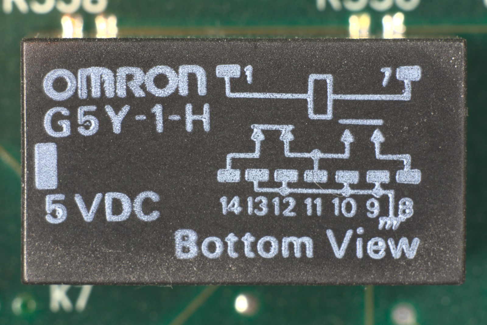
It's an Omron G5Y-1-H: obselete since 2012 and understandably no longer available from Keysight. The "H" suffix indicates this is a "high sensitivity" type, with a coil that draws only 40 mA instead of the standard model's 60. It also has excellent insertion loss and isolation specified up to 900 MHz.
After checking that the relay coil never fires during the power-on self-test, I shorted the two NC contacts with tweezers during power-up. All self-tests passed! This relay is definitely defective, showing completely open between the NC contacts. I even tried cycling the relay a few tens, then hundreds, then thousands, of times through the GPIB interface to no avail.
Since a genuine new part is unobtanium and nothing else fits its footprint anymore, I scoured distributors for modern SMD relays that would fit on a small daughterboard to adapt their pinout to the G5Y's. Unfortunately none of the modern SMD relays that would mechanically fit have close to the same isolation as the G5Y. The only rivals such a "large" relay has in the surface mount form factor are solid state RF switches, if it weren't for their higher insertion loss. I'm picking that low insertion loss is less important than good isolation in the case of this relay. Poor isolation could lead to crosstalk between channels, resulting in noisy triggering (and thus noisy measurements). I haven't run the numbers though.
I didn't see the value in doing deeper analysis on the frontend to see what tradeoffs can be made in relay performance, so I found a pair of genuine-looking new-old-stock G5Y-1 parts from the grey market. Since these aren't the "H" suffix parts, they will have a higher internal heating (300 mW instead of 200) due to the higher coil current. However, the 60 mA coil current is well within the capability of the driver (ULN2003AD or MC1413DG).
K7 Relay Replacement
The NOS G5Y relays arrived by post from the United States this week just gone. Time to desolder the old relay and install the new! Unfortunately the boards HP used in these counters are a bit sensitive to heat and discolour slightly when reworked. This, coupled with the extreme magnification makes it look like I was more harsh with the iron during removal, as well as worse at cleaning and soldering, than I actually was.
The magnification and perspective really make these joints look far worse than they are. By eye with modest magnification they are nice and smooth, I promise. Of course after removal, the old K7 relay decided to test fine with the ohm meter. No doubt the heat during desoldering "fixed" whatever issue it had, but it still can no longer be trusted. Maybe it will make a good teardown candidate someday.
While I was inside the counter, I also corrected the wonky resistor, otherwise it would always be in the back of my mind. Again, the extreme magnification shows how hard it is to clean a board even when you think you're already being thorough. Just look at those dust/paper fibres!
Results
After K7's replacement, let's try the same experiment as before: counting the 10 MHz reference out with Channel 2. Power the unit on:

Hooray! Let's check the input to U54A:
...and of course it's nice and strong now the relay is doing its job, so the display shows the count correctly:

Checking some of the functions that exercise K7 (CH1 duty etc) shows it functions properly in both positions.
A successful repair that saved the unit from scrap.